Thermal Spray FAQs
Home / Thermal Spray FAQs
Thermal spraying is a general classification describing a collection of surface engineering processes in which material is heated and accelerated to be deposited onto a surface, generically referred to as a substrate.
Thermal spray processes are used to add material to worn or damaged components to enable machining back to the original dimensions. Thermal spray processes are also used to enhance component performance through the application of a coating (typically only on specific sections of a component) to improve properties such as abrasion/wear resistance, corrosion resistance, electrical insulation, or thermal insulation.
In a thermal spray process the material, or feedstock, that will form the coating is fed to a device referred to as a gun or torch. At the gun/torch the feedstock is heated and entrained into a gas jet that transports the feedstock to the component being coated. Typically, the feedstock heating and transport processes occur simultaneously because the gas leaving the gun/torch is hotter than the temperature of the feedstock injected into this jet. At the component surface the feedstock material momentum causes it to separate from the gas flow, impact, and deform on the component surface, producing a structure commonly referred to as a splat. The splat then cools and contracts, causing it to grip the underlying surface. The gun/torch or component is moved to repeat the above process across the area to be coated. Typically this area is covered multiple times, producing a coating structure composed of layers of splats.
With most thermal spray coatings, splats adhere to the component surface and to other splats primarily by mechanical forces, which differentiates thermal spray coatings from those of welding, cladding, electroplating, or vapor deposition processes wherein chemical bonds link the atoms within the coating to each other and to atoms along the underlying component surface. Because of the mechanical adhesion mechanism, a component surface is typically roughened before applying a thermal spray coating. Component surfaces are normally roughened by abrasive grit blasting, but in rare cases an acid etch or water jet blasting is used.
Within the thermal spray field, processes exist to produce coatings from materials in the form of powder, wire, rods, suspensions, and solutions. Additionally, thermal spray processes can usually be performed in standard atmospheric conditions or in chambers providing vacuum or inert gas conditions. Therefore, in theory thermal spraying can be used to produce a coating from almost any material. However, in practice, a successful thermal spray coating requires a balance between the physical properties of the coating and the component.
For example, a high melting temperature ceramic coating is unlikely to be applied successfully to a low melting temperature polymer component because the ceramic must deform onto the polymer surface, which would require heat and/or velocity conditions that would damage the component. Another frequently encountered problem for thermal spray coatings is thermal expansion differences between the coating and the underlying component surface. During the spraying process, the component surface and the coating being applied typically reach temperatures that are many times higher than the temperature the coated component equilibrates to after spraying. Thus, the cooling after spraying results in contractions that will generate stresses in the coating and component if these two layers want to contract to different extents. These stresses can cause the coating to crack and lose adhesion to the component surface.
The following table shows the most popular thermal spray processes, lists the temperature and velocity ranges in each process, and summarizes the method by which these conditions are produced.
| Gun description | Heat | Velocity |
|---|---|---|
| Flame |
Gas temperature range: 4,600–5,200°F
Fuel gas is burned with oxygen to melt a continuously fed wire, powder or rod. |
Particle velocity range: 300–800 fps
Expanding combustion gases and compressed air. |
| Wire arc |
Gas temperature range: 10,000–12,000°F
High voltage arc struck between two electrically conductive feed wires turns wire into molten metal. |
Particle velocity range: 500–1,000 fps
Compressed air blown behind the wire intersection sprays atomized molten metal onto the substrate. |
| Plasma |
Gas temperature range: 30,000+°F
High voltage arc created in an atmosphere of monatomic (Argon and Helium) or diatomic (Nitrogen and Hydrogen) gases causes electrons to be pulled from the gas which then releases intense heat (and light) when the electrons rejoin the ions. Depending on the dwell time the powder experiences in the plasma plume, the powder may be semi-molten or molten as it leaves the nozzle. |
Particle velocity range: 800–1,800 fps
The ionization process creates both heat and mechanical energies inside the gun mixing chamber. |
| HVOF (High Velocity Oxygen Fuel) |
Gas temperature range: 6,000+°F
The controlled combustion of fuel (liquid or gas) in an oxygen rich combustion chamber creates high temperature combustion gases. |
Particle velocity range: 2,400–3,200 fps
The combustion process creates rapidly expanding gas in the combustion chamber that results in a very high velocity gases. |
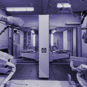
Progressive Surface is primarily an integrator of equipment covering all aspects of thermal spraying:
- Part preparation (grit blasting, CO2 blasting, etc.)
- Part handling (automated loading/unloading of parts linked to process recipe/program changes)
- Part/gun manipulation during spraying
- Feedstock delivery (powder, suspension, solution, etc.)
- Process control (closed-loop computerized control of gases, power, feedstocks, etc.)
- Process recording (run summary reports and second-by-second data logging of process variables)
- Process diagnostics (alarms for abnormal operation, particle speed/temperature sensors, etc.)
- Part temperature monitoring and control
- Acoustic enclosures
- Atmospheric controls (dust collection, engineering safety controls connected to gas levels)
We integrate all commercially available plasma, twin wire arc, combustion powder, combustion wire, and gaseous fuel combinations for HVOF or HVAF systems, and in most cases we can build the control systems to provide functionality beyond the standard commercial unit for a specific torch. Our focus is providing customized equipment to solve the specific needs of our customers. All equipment if fully assembled and tested at our facilities before shipping. We offer supervised or turnkey installation, onsite training, and worldwide service and support.
Our Process Development department can produce most compositions and types (APS, SPS, or SPPS) of plasma spray coatings in standard atmospheric conditions for the purpose of generating test samples. However, at this time Progressive Surface does not offer commercial-scale coating application services.
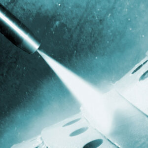
Yes, Progressive Surface offers high pressure waterjet stripping services for the removal of thermal spray coatings.
Electronic principles play a larger role in arc stabilization with the Triplex™ and Sinplex™ designs than they do in the Progressive Surface 100HE plasma spray torch design, which relies primarily on the plasma forming gas flow to stabilize the arc. The gas flow stabilization design reduces the number of torch components and increases operational robustness against factors such as moisture inside the torch, which can often occur when spraying suspensions or solutions.
SPS coating production occurs according to the same principles as in conventional APS; therefore, SPS can be considered to be a variation of APS. The difference between these two processes is in the method for transporting powder to the plasma. With APS the powder particles are entrained in a gas (referred to as a carrier gas) that transports the powder into the plasma. With SPS the powder particles are entrained in a liquid (referred to as the suspension solvent) that transports the powder into the plasma. Consequently, SPS feeders and injection equipment differ from that for APS.
Suspending powder in a solvent facilitates and permits the use of small powder particle sizes that do not flow freely in the dry state and thus are difficult or impossible to convey with APS feeders. While smaller powder sizes permit the production of coating structures not possible with APS, the associated solvent also introduces a penalty because this liquid must be vaporized before the powder can be softened or melted. As a result, an SPS coating requires more enthalpy per gram of deposited mass than an APS coating of the same composition. Furthermore, decreasing the particle size increases the powder sensitivity to ambient temperatures, so SPS standoff distances tend to be significantly shorter than APS standoffs in order to minimize the resolidification of the molten powder before substrate impact.
In SPPS, an entirely liquid mixture is injected into the plasma. The plasma heat causes the solution to transform into a solid material of a different composition which is the one desired for the coating. If this transformation occurs entirely inflight to the substrate, the coating is formed by the impact and solidification/cooling of molten droplets, as in APS. However, the final stages of the transformation can also occur after substrate impact.
Transformational changes on the substrate surface can be a source of internal coating stresses that are not present in the APS process. The use of a liquid feedstock also produces other differences between APS and SPPS. SPPS requires different feeding and injection equipment; this equipment can be the same as that used for SPS. The addition of endothermic feedstock processes (evaporation, precipitation, etc.) before melting results in SPPS requiring more enthalpy per gram of deposited coating than the same composition of APS coating. SPPS solution droplets sizes injected into the plasma tend to be smaller than APS powder particles in order to increase transformation kinetics. This smaller size increases the sensitivity of the droplet to ambient temperatures. Thus, to maximize the deposition of molten material and/or to promote the transformation of solution material on the substrate, SPPS typically involves significantly shorter standoffs than APS.
